
The DvZ MicroFET Board
Introduction
About the Board
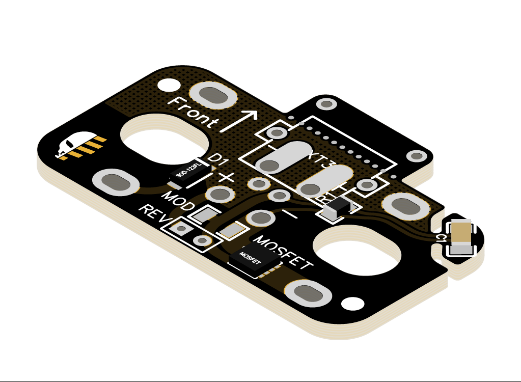
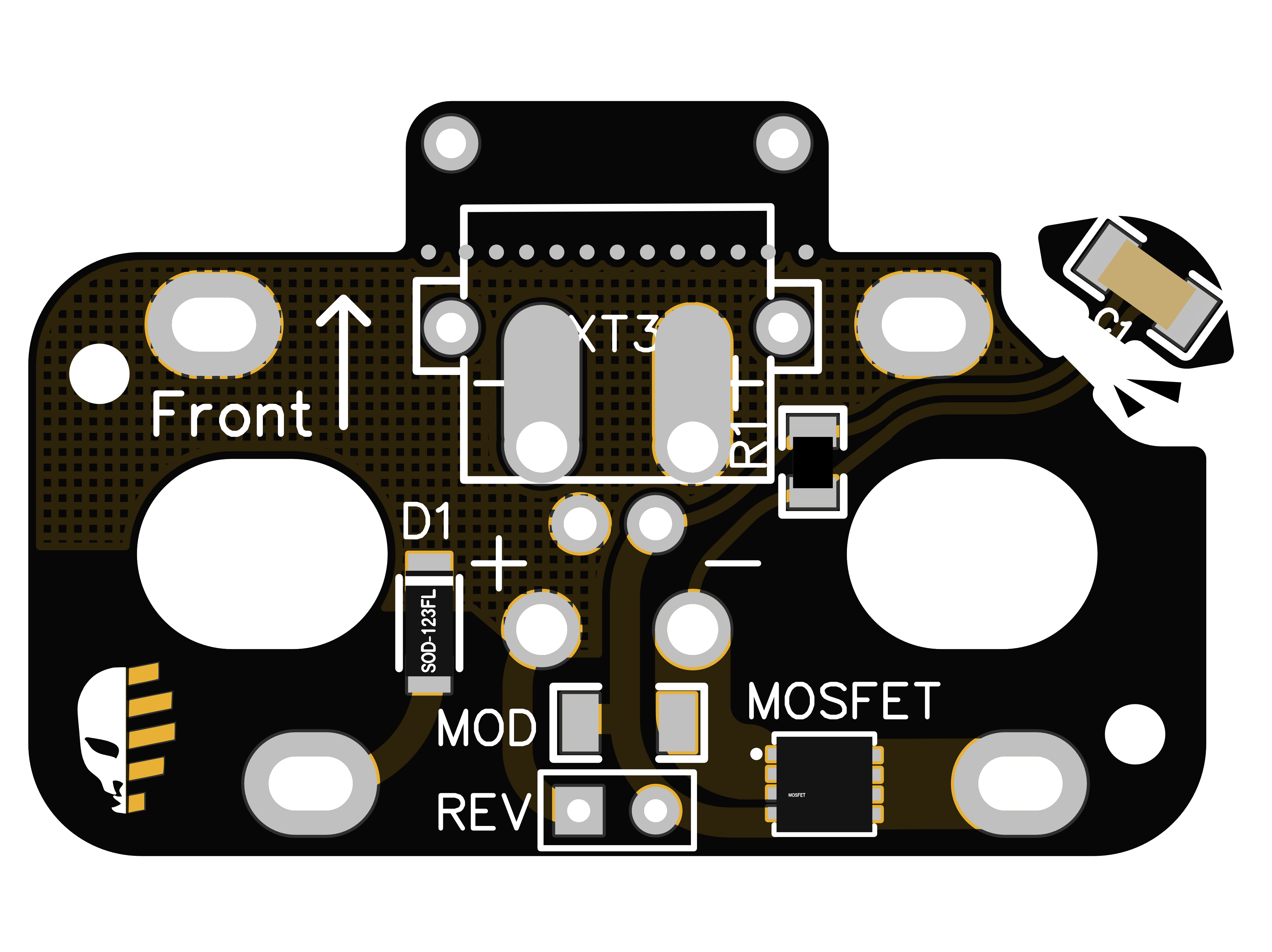
The MicroFET PCB is a Microwheel Motor Spanning Board with Integrated MosFET and optional Shut-Off Delay. It offers many different attachment options for your wiring, including footprints for two surface mount XT30 connectors and a 90° JST plug for the rev trigger.
The MosFET is rated for 30V×120A and should be suitable for any enthusiast grade motor you‘d want in a Microwheel build.

What are Microwheels?
Microwheels were coined by Flywheel the World (FTW) from Australia, but there are compatible wheels from other makers as well. There are many 3D printable blasters that made good use of their small form factor.
What is a Motor Spanning Board?
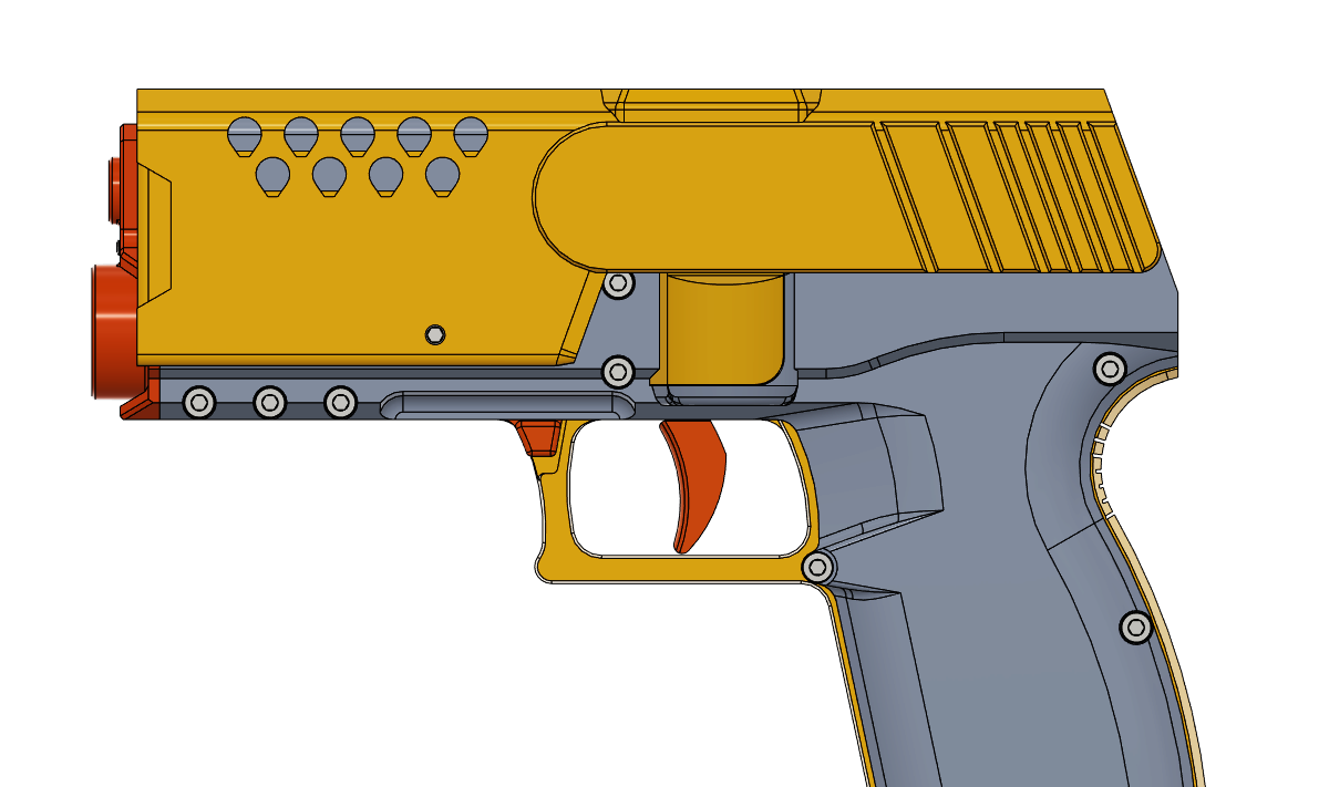
A Motor Spanning Board is mounted directly to the motor contacts on the flywheel assembly, which is otherwise rather tedious to do. The board takes power directly from the battery and the switch (or multiple switches, like a safety) can be hooked up with thinner wiring. Once the prototype arrives i can send you some pictures on how it sits in a blaster.
Why use a MosFET?
The switches we use in the hobby are usually rated for 5A or 15A, while some motor pairs can draw current spikes of 80A or more. That means either the motor current gets limited by the switch, or the switches burn up at some point. A MosFET can be used like a valve to protect your switch and make sure your motors get all the power they need.
Vendors
Installation
Motor Orientation
The PCB has two dot markings by the Motor Pads, but later I realized that motors are often not marked consistently, varying from different manufacturers or even production lines. I’ve found Foamblast and OOD motors to be marked consistent with the mabuchi fk-130 specification and inverse of the markings I put on the PCB.
Testing Motors is easy with a leftover alkaline battery pack and some alligator clips. It is much more work to dismantle your assembly and reverse a motor than it is to confirm it’s spinning in the right direction from the start.
Preparing the PCB
The Boards were manufactured on breakaway panels, which results in residue of the breakaway tabs that might need to be cleaned up. For this, a file, hobby knife or sandpaper can be used.
Wiring and Connectors
It is recommended to solder any connectors before mounting the PCB.
The Board supports front facing XT30 connectors (XT30-PW-M) either on top of, or below the PCB. Please look at the marking on the Board and make sure to use the correct footprint for each connector position or the polarity of your connector may be reversed.
If no Connector is desired, Wires can be soldered to the Elongated Pads on the top or bottom side of the PCB. The Front facing protrusion of the PCB can be snapped off if the bottom-side XT30 is not mounted.
A 90° JST Plug (i.e. “S2B-XH-A(LF)(SN)”) for the rev switch can be soldered to the two pads in the very centre of the Board in any orientation. To attach the switch leads directly, a duplicate footprint is also available towards the rear edge of the board.

Soldering the Board
If your PCB came with silicone or printed insulators, place them over the motor end bells before proceeding.
Seat the PCB on the motors with the component side up and the Arrow marking facing the front of the blaster and mount it by soldering the motor tabs. Especially if there is no insulation, make sure to not use too much solder that could cause a short to the motor can.
Shut-Off Delay
How It Works
A unique feature of the MicroFET is its Shut-Off Delay Circuit that will keep your motors running just a little while after releasing the rev trigger. It greatly improves performance of repeated shots from a single trigger semi-auto setup where fully releasing the trigger between shots would stop the motors.
The delay feature does not increase the time it takes for your flywheels to activate and spin up.
Delay Timing
By default the delay is set to half a second but can be modified by adding a capacitor or resistor to one of the unpopulated „Mod“ footprints on the Board.
| Added Component | Component Value | Resulting Delay |
| None | 0.5s | |
| Resistor | 41.2kOhm | 0.25s |
| Capacitor | 22uF | 1s |
| Capacitor | 47uF | 1.5s |
Disabling the Delay-Feature
If the feature is not wanted it can be easily removed by snapping off the front right corner with the capacitor on it. To achieve a clean break, score the top side of the board to break the traces running to the capacitor before snapping off the section.
Hi, may I know how to wire for the delay to work, as in which holes goes to the switch and which one to the lipo?